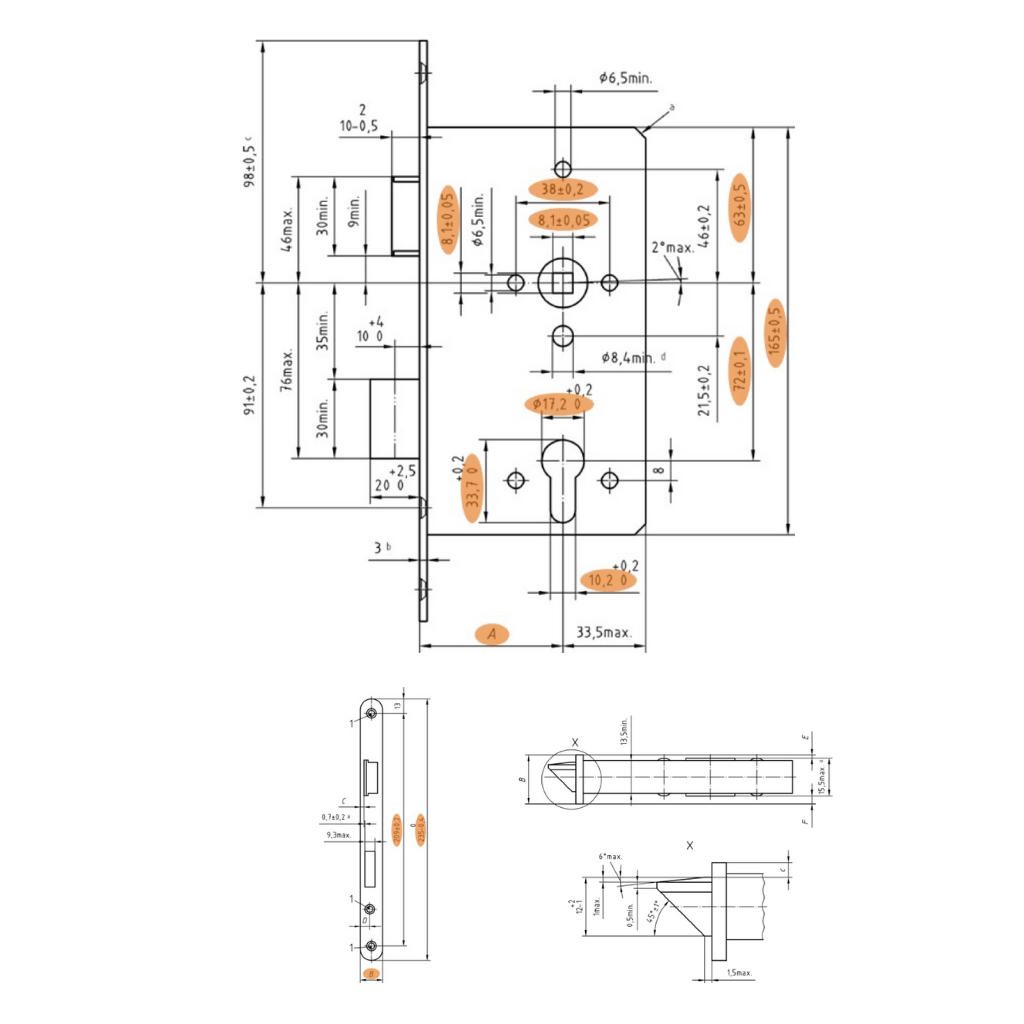
To ensure that the mortise locks implemented in this project work smoothly with the other components of the door set (cylinders and handles), all dimensions of the lock need to be according to the standard DIN 18251-1:2002.
The supplier is responsible to produce only products which meet this requirement.
The following drawing shows the key dimensions for the standard mortise locks:
Lockcase Fixing Instructions
Suitable for use on fire/smoke door assemblies of an identical construction, mode and size as tested – check manufacturer for details.
The fire resistance of the door assembly must not be negated by the fitting of the latch/lock. Any intumescent material required to allow the fire rating to be achieved must be fitted. When installing in a fire rated door to EN 1634, the lockcase must be bedded on to an Interdens intumescent seal, 1mm thick. Sufficient space must be allowed in the preparation of the door to facilitate this.
Resistance to closing of the door by latches, hinges etc. must be controlled to enable the door assembly to fulfil its design function.
These instructions cover the installation of lockcases with 55 and 60mm backset, and either 20 or 24mm forend width. It is essential to identify which size is being fitted. When using templates which suit multiple lockcase types, check which preparations are required according to the lock type being fitted – NOT ALL HOLES MAY BE REQUIRED.
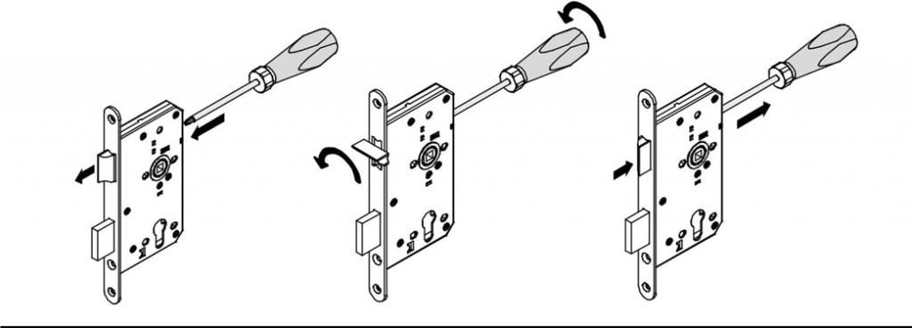
Changing the lock handing:
If requrired, the lock handing can be easily changed by following these simple instructions.
1.Locate the latch release screw which can be accessed from the back edge of the lockcase.
2. Using a pozidri screwdriver push forward on the screw until the latch is free of the forend.
3. Rotate clockwise 180o and release the screwdriver, allowing the latch to withdraw back into the lockcase.
Installation Instruction:
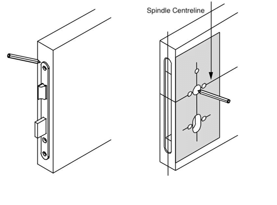
1.Mark on the door the vertical centreline and the required centreline of the spindle/lever handle on both sides of the door.
2.Carefully position the lockcase as shown aligning the centre lines and mark around the lockcase on the door edge.
3.Mortice out the door to allow the lockcase to slide in ensuring a good fit but not too tight.

4.With the lockcase inserted into the door, mark around the forend. Remove the lock and prepare a recess 3mm deep to allow the lock forend to sit flush with the door edge.
5.Place or tape the relevant template in position on the door face aligning the spindle centreline with the markings on the door.Mark the position of the spindle and cylinder and any through fixing holes required making sure to use the correct template markings for the lock being fitted.You can repeat this on the other side of the door.
6.Drill all required holes from both sides of the door through into the mortice.
7.Remove all debris from the mortice and fix the lockcase into position with the screws provided.
CHECK THE LOCK OPERATES CORRECTLY
Installation of Strike plate
8.Close the door up to the frame and mark the position of the latch and/or bolt (depending on the lock being fitted) onto the frame. Transfer the lines around to the inside edge of the frame [a].
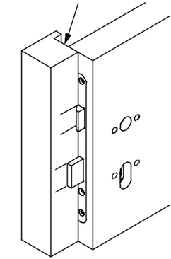
9.Measure the distance [b] from the closing face of the door to the edge of the latch/bolt and mark this distance onto the frame so that the latching/locking positions are accurately transferred to the frame.

10.Position the strike plate on the frame so that the markings of the latch/bolt position can be seen through the apertures on the strike plate.
11.Mortice out the frame for the latch and/or bolt and recess the frame so that the strike plate sits flush with the frame. The screw holes may need to be counter-bored to allow the strike plate to lie flush.
12.Fit strike plate with the screws provided.
13.Fit furniture as required and check the operation of the lockcase.
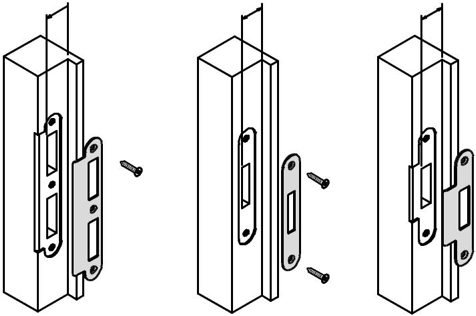
PLEASE NOTE, THE DEADBOLT OF YHE SASHLOCKS AND DEADLOCKS HAVE A THROW OF 20MM. ENSURE SUFFICIENT MATERIAL IS REMOVED FROM THE FRAME TO ALLOW THE BOLT TO THROW TO ITS FULL EXTENT INTO THE FRAME.
For more information, pls check the video from our Youtube channel or contact us by:
Mobile/Whatsapp: +86 13693395023
Email: info@euprotek.com

1人评论了“How to Install a Euro Mortise Door Lock?”
A round of applause for your blog post. Really looking forward to read more. Great. Nelson Aydt